

What's included in this White Paper?
A distilled overview of the concepts and terminologies that make up ACI (SDN for Data Centre) and more detail around how a Multi-Pod ACI implementation functions.
- Specific concepts and terminologies explained
- Overview of the different technologies involved
- How do these technologies fit together?
Download White Paper: ACI (SDN for your Data Centre) Demystified
A distilled overview of the concepts and terminologies that make up Application Centric Infrastructure (SDN for Data Centre) and more detail around how a Multi-Pod ACI implementation functions.
DownloadIntroduction
How does Application Centric Infrastructure (ACI) coincide with the context of Local Area Networks (LAN) and Wide Area Networks (WAN)?
As a follow on from the previous software defined white paper, this white paper seeks to attempt to place Application Centric Infrastructure (ACI) terms and concepts into the context of traditional Local Area Network (LAN) and Wide Area Network (WAN) concepts. In this paper we will focus on general terms that crop up in ACI and how a Multi-Pod ACI implementation functions.
ACI Multi-Pod Deployment
Download White Paper: ACI (SDN for your Data Centre) Demystified
A distilled overview of the concepts and terminologies that make up Application Centric Infrastructure (SDN for Data Centre) and more detail around how a Multi-Pod ACI implementation functions.
DownloadACI Policy & Control Plane Concepts
The Application Policy Infrastructure Controller (APIC) is the management and policy plane of ACI. It controls how each switch behaves within the network, which in ACI speak is known as a fabric. The functions of a fabric are based on a set of user created policies, which are usually referred to as the Policy Plane.
The APIC also controls the physical addressing of the switches from a Tunnel Endpoint (TEP) point of view. The APIC runs a Dynamic Host Configuration Protocol (DHCP) server that hands out addresses to the spine and leaf switches, it should be noted that APICs are connected to leaf switches. In Virtual Extensible LAN (VXLAN) a Virtual Tunnel Endpoint (VTEP) is used in the terminology to describe the VXLAN tunnel source and destination.
TEPs form the tunnel source and destination addresses to carry overlays
An Endpoint Group (EPG) is a collection of hosts (that can be micro-segmented) that live in a Bridge Domain, EPGs work in almost the same way as Security Group Tags (SGT) in TrustSec, in fact they do if you integrate Identity Services Engine (ISE) with ACI. Think of EPGs as static / dynamic groups in ISE or the policy part of Virtual Networks (VN) in Software Defined Access (SD-A). A Bridge Domain (BD) is just a Virtual LAN (VLAN) that share common layer 2 broadcast domains for the EPGs to talk to each other (or not). From a layer 3 perspective a BD can have associated subnet objects (it needs at least one, with the exception of a pure L2 VLAN) and needs to be in a Virtual Routing and Forwarding (VRF) instance. But both the VRF, BD and subnet are separate entities so you need to associate them with each other, it’s common to have multiple BDs and subnets in a VRF, just like a traditional LAN.
A BD can be set to operate in flood mode for unknown unicast frames or in an optimised mode which eliminates flooding for these frames. When operating in flood mode, Layer 2 unknown unicast traffic is flooded over the multicast tree of the bridge domain (Group IP Outer (GIPo)). For the bridge domain to operate in optimised mode you should set it to hardware-proxy. In this case, Layer 2 unknown unicast frames are sent to the spine-proxy anycast VTEP address.
Each BD has associated a separate multicast group (GIPo) to ensure granular delivery of multi-destination frames only to the endpoints that are part of a given BD, as within the ACI fabric a BD is not a true broadcast domain like ethernet.
Download White Paper: ACI (SDN for your Data Centre) Demystified
A distilled overview of the concepts and terminologies that make up Application Centric Infrastructure (SDN for Data Centre) and more detail around how a Multi-Pod ACI implementation functions.
DownloadACI Policy & Control Plane Concepts
If IP routing is enabled in the BD, the mappingdatabase learns the IP address of the endpoints in addition to the MAC address. These are the supported Layer 3 Configurations for BDs:
- Unicast Routing: If this setting is enabled and a subnet address is configured, the fabric provides the default gateway function and routes the traffic. Enabling unicast routing also instructs the mapping database to learn the endpoint IP-to-VTEP mapping for this BD. The IP learning is not dependent upon having a subnet configured under the BD.
- Subnet Address: This option configures the Switched Virtual Interface (SVI) IP addresses (default gateway) for the BD.
- Limit IP Learning to Subnet: This option is similar to a unicast reverse-forwarding-path check. If this option is selected, the fabric will not learn IP addresses from a subnet other than the one configured on the BD.
You can associate multiple subnets with a single BD, but just like with a traditional campus LAN, in practice though, it’s normally a good idea to maintain a 1:1 relationship between BDs and Subnets.
A VRF is a process of logical segregation of the control and data planes. A VRF creates a separate instance of a routing table and control plane protocols (if any) that go along with it. It’s usual to have multiple BDs and subnets in a single VRF, as grouping hosts and networks together that have a single purpose is advantageous from a scalability perspective.
In the APIC GUI a VRF is also called a ‘context’ or ‘private network’
A BD that has an associated subnet has an anycast address that functions as the gateway for that BD, so the anycast gateway only does something when your traffic originates from one BD to another BD in the same VRF or between BDs in different VRFs.
It’s common to have a single shared BD (VLAN) that has multiple EPGs, for example; a services BD that contains Network Load Balancers (NLB) and security appliances. The NLBs would be in the NLB EPG and the security appliances would be in the Security EPG, communication between these hosts in the different EPGs would require a contract.
A contract is the policy plane of ACI, EPGs can only communicate with other EPGs according to contract rules. Contracts select the type(s) of traffic that can pass between EPGs, including the protocols and ports allowed. If there is no contract, inter-EPG communication is disabled by default. There is no contract required for intra-EPG communication; intra-EPG communication is always implicitly allowed, contracts also allow EPGs to talk to L3 outs.
The options for a subnet under a BD or under an EPG are as follows:
- Public – the subnet can be exported to a routed connection.
- Private – the subnet applies only within its tenant.
- Shared – the subnet can be shared with and exported to multiple VRFs in the same tenant or across tenants as part of a shared service. An example of a shared service is a routed connection to an EPG present in another VRF in a different tenant. This enables traffic to pass in both directions across VRFs. An EPG that provides a shared service must have its subnet configured under that EPG (not under a BD), and its scope must be set to advertised externally (which is a check box on the APIC), and shared between VRFs.
- Intra – EPG endpoint isolation policies provide full isolation for virtual or physical endpoints; no communication is allowed between endpoints in an EPG that is operating with isolation enforced. Isolation enforced EPGs reduce the number of EPG encapsulations required when many clients access a common service but are not allowed to communicate with each other, an isolation enforced EPG is basically a Private VLAN (PVLAN).
Download White Paper: ACI (SDN for your Data Centre) Demystified
A distilled overview of the concepts and terminologies that make up Application Centric Infrastructure (SDN for Data Centre) and more detail around how a Multi-Pod ACI implementation functions.
DownloadACI Traffic & Data Plane Concepts
L3 outs are a collection of settings that allows the fabric to talk to other networks (off fabric traffic), L3 outs are also technically VRFs, but seeing as they are point to point (are explicitly associated with a leaf, more usually with a Virtual Port Channel (vPC) pair of leaves for Multi-Chassis Port Channel (MCPC) they don’t have to have an anycast SVI address.
L3 outs also require a special EPG called an external EPG. The routes injected into the fabric are placed into the VRF (associated with the sending / receiving BD / EPG) by Multiprotocol Broader Gateway Protocol (MBGP) with the spine acting as the route reflector (but MBGP only comes into play when a L3 out is used).
L3 outs can be any protocol supported by ACI, but it’s always redistributed into MBGP inside the fabric. You can also have an L2 out as well, it’s perfectly valid to stretch the BD outside of the fabric without an L3 out, in the case of an L2 out the VXLAN is decapsulated to just plain old ethernet when it egresses the L2 out on the leaf (leaf vPC pairs).
From a control plane perspective it looks like this:
- Underlay = IS-IS
- Intra fabric overlays (BDs, VRFs etc) within ACI = Council of Oracles Protocol (COOP)
- Off fabric overlays (L3 outs) = MBGP (routes are redistributed into MBGP from the L3 out)
- Interpod / intersite overlays = MBGP Ethernet Virtual Private Network (EVPN) From a data plane perspective: Underlay = ethernet / IP Overlays = VXLAN / IP
From a data plane perspective:
- Underlay = ethernet / IP
- Overlays = VXLAN / IP
Download White Paper: ACI (SDN for your Data Centre) Demystified
A distilled overview of the concepts and terminologies that make up Application Centric Infrastructure (SDN for Data Centre) and more detail around how a Multi-Pod ACI implementation functions.
Download4-Steps to LISP Tunnel Creation
All overlay data planes send VXLAN encapsulated traffic between one tunnel endpoint and another, ACI refers to these as TEPs (or VTEPS), but really they’re just loopback addresses used as the destination and source of the VXLAN tunnel.
COOP is the control plane for intra fabric communication in ACI. When a leaf receives an Address Resolution Protocol (ARP) from a host it looks inside the payload of the ARP packet and learns the IP of the host and copies it to its Local Station Table, and then reports this information to one of the spine switches (chosen at random) using the COOP. The spine switch that was chosen then relays this information to all the other spines so that every spine has a complete record of every endpoint in the system. The spines record the information learned via the COOP in the Global Proxy Table, and this information is used to resolve unknown destination MAC/IP addresses when traffic is sent to the Proxy address. COOP does not require MBGP to function.
A tenant is a logical grouping of all of the above, it’s the container that contains the EPGs, VRFs, BDs, L3 outs, contracts, filters and application profiles. I also like to think of it as a super-VRF that creates a separate instance of the fabric (from a control plane / data plane perspective). Communication between tenants can occur if the BD or EPG are shared, a valid use of this concept is the shared tenant ‘infra’ this can be used to share a single L3 out (normally to the internet, but can be any common outside network) so each tenant uses the shared infra L3 out, but the tenants do not talk to each other, this simplifies the infrastructure.
Download White Paper: ACI (SDN for your Data Centre) Demystified
A distilled overview of the concepts and terminologies that make up Application Centric Infrastructure (SDN for Data Centre) and more detail around how a Multi-Pod ACI implementation functions.
DownloadACI Policy & Control Plane Concepts
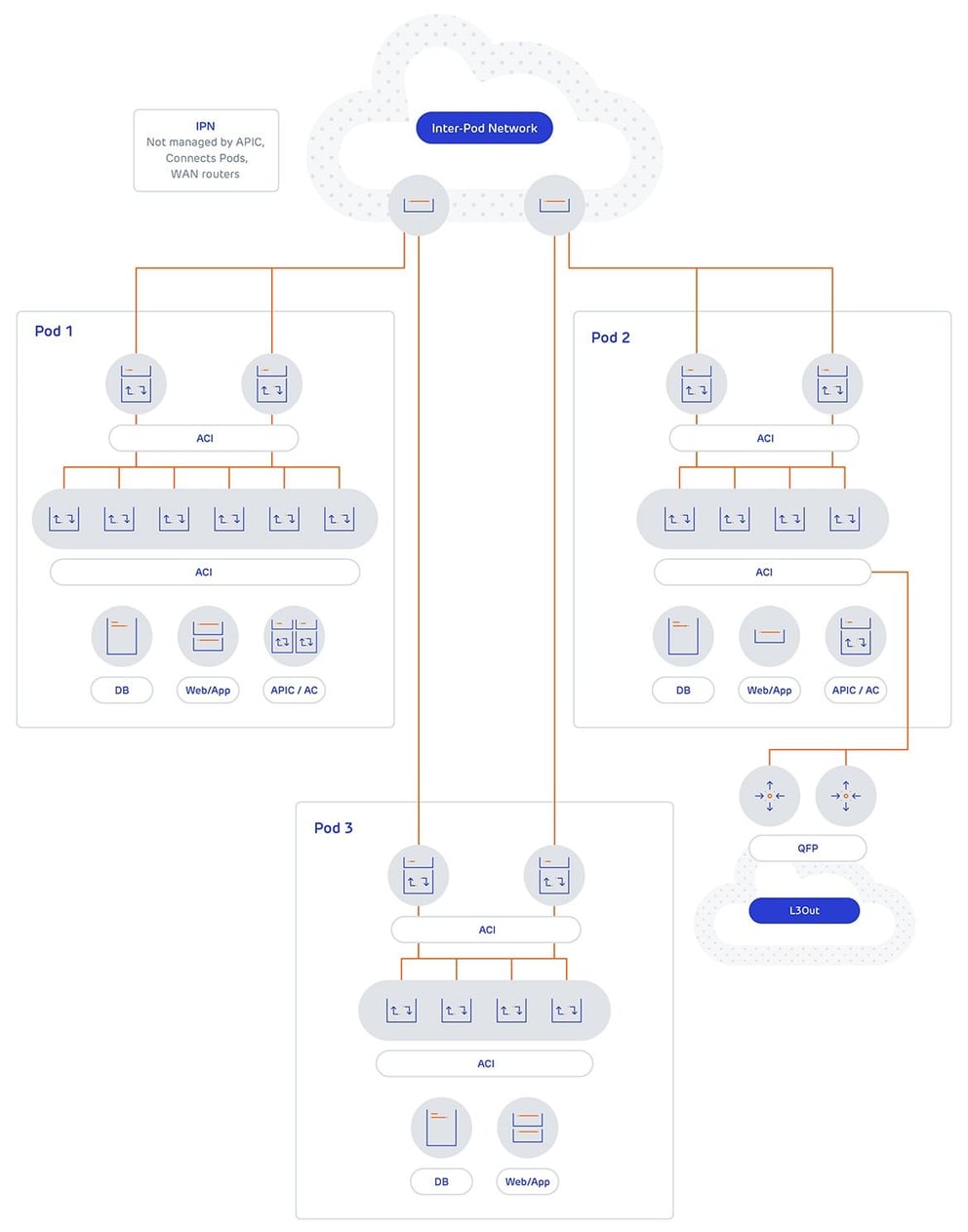
In ACI Multi-Pod it’s a perfectly valid design to have a pod dedicated to external L3 outs, exclusively in its own tenant. ACI Multi-Pod is where the ACI fabric is stretched across multiple physical locations (this can be in the different data halls in the same Data Centre (DC) with separate Leaf and Spine switches, utilising the same APICs. ACI Multi-Pod shares the same APIC failure domain, that is to say all of the pods fate is shared with the policy and management plane.
ACI Multi-Pod is where the ACI fabric is stretched across multiple physical locations (this can be in the different data halls in the same Data Centre (DC) with separate Leaf and Spine switches, utilising the same APICs. ACI Multi-Pod shares the same APIC failure domain, that is to say all of the pods fate is shared with the policy and management plane. ACI Multi-Pod requires an independent network to provide a means of communication, this network is referred to as the IPN (inter POD network). The IPN is not managed by the APIC and can include any switches that support the required features.
The IPN is required to support DHCP relay (the target is the APIC) so additional pods can be discovered, it is required to support jumbo frames and uses Open Shortest Path (OSPF) to peer with the spine switches. The IPN is required to support IP Protocol Independent Multicast (PIM) (sparse mode) to allow the flow of BUM (broadcast, unknown unicast and multicast) traffic (the GIPo of the bridge domain is mapped to a multicast group), which is why the final requirement is that the IPN is required to support PIM Bi-Directional PIM (Bidir) for the GIPo addresses mapped to multicast groups; in reality the internal GIPo addresses are multicast addresses, therefore the mapping is usually 1:1.
IP PIM Bidir is required so that a single multicast tree is used for all multicast groups, Bidir limits the PIM process to mapping the specified multicast groups (the GIPo addresses for all BD’s) to the (* , G) shared tree. This way multiple inter pod BDs do not require multiple (S , G) trees to be built to support interpod BUM traffic. When a BD spans multiple pods, a random spine in the pod will become the designated sender and the spine switch then sends an Internet Group Membership protocol (IGMP) join message to the IPN node for the BD GIPo multicast group. When BUM traffic is sent between BDs in different PODs, it is encapsulated into VXLAN with a destination of the multicast group address. It is then multicast routed across the IPN to the designated receiving spine switch, and then sent to the fabric internal GIPo address associated with the BD.