

What's included in this White Paper?
This third white paper in the series on Software Defined (SD) technologies aims to cover the technical terms used in SD-WAN, what they mean and how they fit together. We will also look at how the Primary SDN Components contribute to the efficiencies and benefits of utilising SD technologies.
- In-depth explanation of technical terms used in SD-WAN
- Insight into how the concepts fit together in the SD landscape
- Exactly how do vSmart, vEdge, vBond and vManage interlink?
Download White Paper: SD-WAN Technical Concepts
This third white paper in the series on Software Defined (SD) technologies aims to cover in more detail some of the technical terms used, what these actually mean, the concepts they cover and how they fit together in the SD landscape.
DownloadIntroduction
This third white paper in the series on Software Defined (SD) technologies aims to cover in more detail some of the technical terms used, what these actually mean, the concepts they cover and how they fit together in the SD landscape.
We will see exactly how vSmart, vEdge, vBond and vManage interlink and how the services used to manage these components and systems contribute to the efficiencies and benefits of utilising SD technologies.
SD-WAN Technical Concepts
There are various technical terms used in SD-WAN todescribe networking concepts which may be familiar, as they have direct analogues in traditional networking and quite a lot in common with WAN delivery methods such as DMVPN (Dynamic Multipoint Virtual Private Network).
- vSmart The vSmart controller is the brains of SD-WAN, it is the centralised policy controller and delivers the control plane for all connected SD routers in the domain.
- vEdge The vEdge is the SD-WAN router, it’s software and can be hosted on multiple device types including certain hypervisors.
- vBond The vBond is part of the orchestration and zero touch deployment of SD-WAN, a vBond tells the vEdge which vSmart will be responsible for its configuration and policies.
- vManage The vManage is the policy and management plane (interface) for the whole SD-WAN environment. The vManage interface allows a single point of management for the whole SD-WAN.
Domain ID
A domain is a logical grouping of vEdge routers and vSmart controllers that demarcates the span of control for the vSmart controllers.
Each domain is identified by a unique integer, called the domain ID. Currently, you can configure only one domain in an SD-WAN overlay network.
Within a domain, vEdge routers can connect only with the vSmart controllers in their own domain. The vBond orchestrator is aware of which vSmart controllers are in which domain, so that when new vEdge routers come up, the vBond orchestrator can point those routers to the vSmart controllers in the proper domain. However, the vBond orchestrator is never a member of a domain.
Within a domain there is full synchronization of routing information among the vSmart controllers and vEdge routers, and there is scope for route aggregation and summarization. An organization can divide up its network into domains to serve desired business purposes. For example, domains can correspond to a large geographic area or to data centers so that each data center and the branches for which it is responsible are contained within a single domain.
Download White Paper: SD-WAN Technical Concepts
This third white paper in the series on Software Defined (SD) technologies aims to cover in more detail some of the technical terms used, what these actually mean, the concepts they cover and how they fit together in the SD landscape.
DownloadSystem IP Address
Each vEdge router and vSmart controller is assigned a system IP address, which identifies the physical system independently of any interface addresses.
This address is similar to the router ID on a regular router. The system IP address provides permanent network overlay addresses for vEdge routers and vSmart controllers, and allows the physical interfaces to be renumbered as needed without affecting the reachability of the SD-WAN device. You write the system IP address as you would an IPv4 address, in decimal four-part dotted notation.
Transport Location (TLOC)
A TLOC identifies the physical interface where a vEdge router connects to the WAN transport network or to a NAT gateway. A TLOC is identified by a number of properties, the primary of which is an IP address–colour pair.
Colour
In the APIC GUI a VRF is also called a ‘context’ or ‘private network’
Overlay Management Protocol (OMP)
The SD-WAN overlay networks are controlled by OMP, effectively this is the control plane of SD-WAN overlay routing. OMP allows the building of scalable, dynamic, on-demand, and secure VPNs.
SD-WAN uses a centralised controller for easy orchestration, with full intent based policy control that includes granular access control and a scalable secure data plane between all edge nodes. SD-WAN allows edge nodes to communicate directly over any type of transport network, consumer grade public internet connectivity, business grade public internet connectivity metro Ethernet, MPLS or LTE.
OMP is the protocol responsible for establishing and maintaining the SD-WAN control plane, as such it provides the following services:
- Orchestration of overlay network communication, including connectivity among network sites, service chaining, and VPN topologies.
- Distribution of service-level routing information and related location mappings.
- Distribution of data plane security parameters.
- Centralised control and distribution of routing policies.
On vSmart controllers and vEdge routers, OMP advertises to its peers the routes and services that it has learned from its local site, along with their corresponding TLOC. These are called OMP routes, to distinguish them from standard IP routes. It is through OMP routes that the vSmart controllers learn the network topology and the available service.
The SD-WAN control plane architecture uses three types of OMP routes:
- OMP routes - Prefixes that establish reachability between end points that use the OMP-orchestrated transport network. OMP routes can represent services in a central data center, services at a branch office, or collections of hosts and other end points in any location of the overlay network. OMP routes require and resolve into TLOCs for functional forwarding. In comparison with BGP, an OMP route is the equivalent of a prefix carried in any of the BGP AFI/SAFI (Address Family Indicator/ Subsequent Address Family Indicator) fields.
- TLOC’s - Identifiers that tie an OMP route to a physical location. The TLOC is the only entity of the OMP routing domain that is visible to the underlying network, and it must be reachable via routing in the underlying network. A TLOC can be directly reachable via an entry in the routing table of the physical network, or it must be represented by a prefix residing on the outside of a NAT device and must be included in the routing table. In comparison with BGP, the TLOC acts as the next hop for OMP routes.
- Service routes - Identifiers that tie an OMP route to a service in the network, specifying the location of the service in the network. Services include firewalls, Intrusion Detection Systems (IDS), and load balancers.
Download White Paper: SD-WAN Technical Concepts
This third white paper in the series on Software Defined (SD) technologies aims to cover in more detail some of the technical terms used, what these actually mean, the concepts they cover and how they fit together in the SD landscape.
DownloadSite ID
A site is a particular physical location within the SD-WAN overlay network, such as a branch office, a data center, or a campus.
Each site is identified by a unique integer, called a site ID. Each SD-WAN device at a site is identified by the same site ID. So within a data center, all the vSmart controllers and any vEdge routers are configured with the same site ID. A branch office or local site typically has a single vEdge router, but if a second one is present for redundancy, both routers are configured with the same site ID.
SD-WAN Data plane and security
The SD-WAN implementation of data plane authentication and encryption establishes security associations between each pair of devices that want to exchange data, but it dispenses with Internet Key Exchange (IKE) altogether. Instead, to provide a scalable solution to data plane key exchange, the SD-WAN takes advantage of the fact that the Datagram Transport Layer Security (DTLS) control plane connections in the SD-WAN overlay network are known to be secure. Because the SD-WAN control plane establishes authenticated, encrypted, and tamperproof connections, there is no need in the data plane to set up secure communications channels to perform data plane authentication.
In the SD-WAN network, data plane encryption and key generation are done by AES-256, a symmetric-key algorithm that uses the same key to encrypt outgoing packets and to decrypt incoming packets. Each vEdge router periodically generates an AES key for its data path (specifically, one key per TLOC) and transmits this key to the vSmart controller in OMP route packets, which are similar to IP route updates. These packets contain information that the vSmart controller uses to determine the network topology, including the vEdge router’s TLOC and AES key. The vSmart controller then places these OMP route packets into reachability advertisements that it sends to the other vEdge routers in the network. In this way, the AES keys for all the vEdge routers are distributed across the network. Even though the key exchange is symmetric, SD-WAN devices use it in an asymmetric fashion. The result is a simple and scalable key exchange process that does not use per-pair keys.
SD-WAN feature: Service Chaining
Service chaining allows data traffic to be rerouted through one or more services, such as firewall, load balancer, or IDS without requiring an instance of the services to be physically deployed at each site. Service chaining can allow an SD-WAN deployment to have virtualised instances of a firewall be instantiated using a cloud provision (public or private).
Usually these devices are associated with a physical appliance and are hosted in a resilient pair on each site, the inherent costs of doing so can escalate the per site budget of a branch WAN deployment.
To use service chaining, a resilient pair of virtualised (can be physical, if required) service appliances are provisioned in a centralised public or private cloud instance. Traffic is then seamlessly redirected from a TLOC by a per-VPN service chaining policy to the relevant service appliance. This action allows the service appliance to inspect or load balance the traffic before sending it on to the destination TLOC. The service chaining policy is pushed to the TLOC using OMP from the vSmart. When a service chaining policy requires the traffic to be rerouted to a service, the policy on the vSmart controller changes the next hop for the OMP routes to the service landing point. In this way, the traffic is first processed by the service before being routed to its final destination.
The service chaining policy can reference multiple virtual services appliances, and in combination with orchestration and cloud management technologies, can provision a new firewall service. So, for example if a firewall site exceeds its capacity, it can automatically add a new service to the service chaining policy with a more preferential weighting if required. Similarly, services can be deployed as part of an orchestration workflow, whereby the VPN and service chaining policies use an API to build both the SD-WAN and services layer as part of a single automated provision.
Here are some examples of use cases for rerouting a traffic flow through a service or chain of services:
- A traffic flow from a less secure region of a network must pass through a service, such as a firewall, or through a chain of services to ensure the integrity of the data.
- For a network that consists of multiple VPNs, each representing a function or an organisation, traffic between VPNs must traverse through a service, such as a firewall, or through a chain of services. For example, in a campus, inter-site traffic might go through a firewall, while intra-site traffic might be routed directly.
- Certain traffic flows must traverse a service, such as a load balancer, which can then distribute traffic evenly to the relevant service front end.
Figure 1. Service Chaining
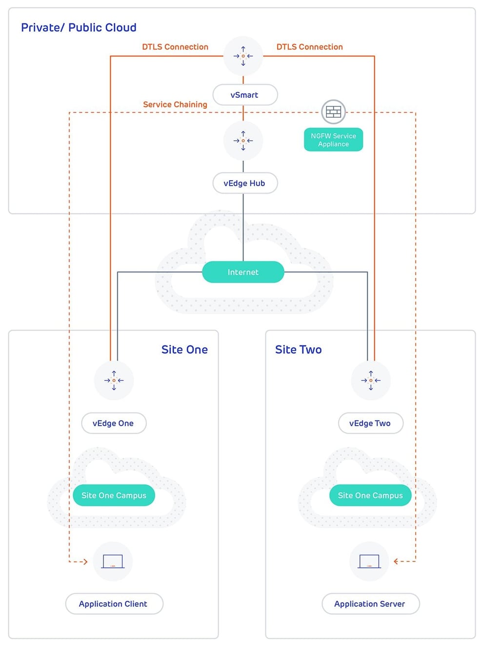
Figure 1. illustrates how service chaining works in the SD-WAN solution. The network shown has a centralized vEdge hub router that is connected to two branches, each with a vEdge router. The standard network design implements a control policy such that all traffic from branch site one to branch site two travels through the vEdge hub router. Sitting behind the hub router is a firewall device. So now, assume we want all traffic from site one to site two to first be processed by the firewall. Traffic from the vEdge router at site one still flows to the vEdge hub router, but instead of sending it directly to site two, the hub router redirects the traffic to the firewall device. When the firewall completes its processing, it returns all cleared traffic to the hub, which then passes it along to the vEdge router at site two.